Table of Contents >> Show >> Hide
- What Makes a Servo-Powered 7-Segment Display Special?
- The Core Build: 28 Servos, Four Digits, One Mechanical Timepiece
- How the Electronics Work
- The Magic Is in the Mapping
- Power: The Part Beginners Should Not Ignore
- Why This Project Feels Like Choreography
- Design Challenges and Practical Fixes
- Why Makers Love Mechanical 7-Segment Clocks
- Specific Example: From 09:59 to 10:00
- Experience Notes: Building, Testing, and Living With a Servo-Powered Chronograph
- Conclusion
Some clocks politely tell time. Others announce it with glowing digits, silent quartz discipline, and the emotional range of a microwave. Then there is the wonderfully theatrical world of the servo-powered 7-segment chronograph: a kinetic timepiece where every number is physically performed by moving parts. Instead of lighting LEDs, each digit is built from seven mechanical segments, and each segment flips into position under servo control. The result is part clock, part robot ballet, and part proof that engineers will happily make timekeeping more complicated if the final result looks this delightful.
The title “Servo-Powered 7-Segments Choreograph This Chronograph” sounds dramatic because the machine itself is dramatic. A conventional 7-segment display uses seven bars to form numbers from 0 to 9. In a mechanical version, those bars are no longer passive lights. They become little actors. A microcontroller decides what digit should appear, servo motors rotate individual segments, and the display changes by physically rearranging itself. The time is not merely shown; it is staged.
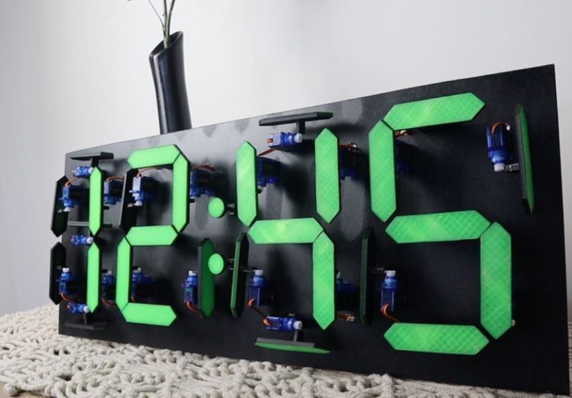
At the heart of many builds in this style is a simple but clever idea: use four 7-segment digits for hours and minutes, give each digit seven movable pieces, and control all 28 segments independently. Add an Arduino, a real-time clock module, and servo driver boards, and suddenly the humble clock becomes a miniature mechanical orchestra. It is not the most efficient way to tell time, but it may be one of the most charming.
What Makes a Servo-Powered 7-Segment Display Special?
A standard 7-segment LED display is a familiar component in digital clocks, calculators, meters, ovens, and alarm panels. Each digit is drawn from seven labeled segments, usually named A through G. Turn on the right combination and you get a number. For example, the digit 1 needs only two vertical segments, while 8 uses all seven. It is beautifully economical, which explains why the format has survived for decades.
A servo-powered version keeps the same visual language but replaces light with motion. Instead of switching an LED on or off, the system rotates a physical segment into either a visible or hidden position. When the segment is “on,” it lies flat and faces the viewer. When it is “off,” it pivots away, often around 90 degrees, disappearing into the background or becoming visually less important. The logic is digital, but the effect is deeply analog.
That mix is what makes the design so satisfying. The viewer instantly recognizes the digits, yet the way those digits appear feels alive. Every minute change becomes a tiny performance. Segments flip, settle, and align. The clock does not just update; it changes its posture.
The Core Build: 28 Servos, Four Digits, One Mechanical Timepiece
A four-digit mechanical 7-segment clock needs 28 movable segments because each of the four digits contains seven bars. In a typical Arduino-based build, each bar is connected to a micro servo. The servo rotates the segment between two positions: one for visible and one for hidden. If the time changes from 12:34 to 12:35, the microcontroller does not redraw a screen. It calculates which segments should move, then commands the relevant servos to reposition.
The structure is usually made with a mix of 3D-printed parts and a rigid back panel such as MDF, acrylic, or plywood. The 3D-printed segments are attached to servo horns, allowing them to pivot cleanly. A good mechanical design must solve several small problems at once: the segments must be light enough for micro servos, strong enough not to warp, spaced well enough not to collide, and aligned precisely enough to look like crisp digits.
This is where the project becomes more than a wiring exercise. A mechanical display has tolerances. Plastic shrinks slightly during printing. Servo arms do not always center perfectly. Screws introduce tiny offsets. A segment that looks perfect on a CAD screen can appear crooked on the finished clock if its zero position is not calibrated. In other words, the software may be digital, but the build has very real-world opinions.
How the Electronics Work
The Microcontroller: The Clock’s Conductor
An Arduino Uno is often enough to control the project because the heavy lifting is handed off to dedicated servo driver boards. The Arduino’s job is to read the current time, translate each digit into a 7-segment pattern, and send commands to the drivers. Think of it as the conductor standing in front of 28 tiny musicians. It does not play every instrument directly; it cues the sections at the right moment.
Without driver boards, controlling 28 servos from a small microcontroller would be inconvenient. A typical Arduino board does not have enough practical PWM-capable pins for that many servos, and timing all those pulses directly can eat into processing resources. This is why PCA9685-based 16-channel PWM boards are a popular choice. Two of them provide 32 channels, leaving a few spares after the 28 servos are connected.
The Servo Drivers: Why PCA9685 Boards Make Sense
The PCA9685 is a 16-channel PWM controller commonly used for servo-heavy projects. It communicates over I2C, meaning the Arduino can control many servo outputs using only two communication pins. Each board generates stable PWM signals for its connected servos, so the microcontroller can focus on deciding what should move rather than constantly maintaining every pulse.
For a four-digit mechanical chronograph, one driver board can handle the hour digits and the other can handle the minute digits. This division keeps wiring organized and makes the code easier to understand. It also mirrors how people read time: hours on one side, minutes on the other, and a colon or separator in between if the design includes one.
The Real-Time Clock: Keeping Time When the Arduino Naps
A real-time clock module, such as a DS1302, lets the project keep track of time independently of the Arduino’s main program loop. This matters because the Arduino itself is not ideal as a long-term timekeeper. It can count milliseconds, but that count depends on the board’s clock accuracy and resets when power is lost. An RTC module uses its own timing circuit and backup battery so the clock can remember the correct time even after the main power is disconnected.
The Arduino reads the RTC, extracts the hour and minute values, then breaks them into four digits. For example, 09:42 becomes 0, 9, 4, and 2. Each digit maps to a segment pattern. The program then looks up which servos belong to that digit and sends each servo to either its active or inactive angle.
The Magic Is in the Mapping
A 7-segment display is simple because every digit can be stored as a pattern. The number 0 uses six segments, leaving the middle bar off. The number 1 uses two. The number 8 uses all seven. In code, these patterns are often stored as arrays, tables, or byte values. In a mechanical display, each segment also needs two calibrated servo positions: visible and hidden.
This creates a useful separation between logic and hardware. The digit pattern says which segments should be on. The calibration table says where each physical servo must move to make that happen. That distinction is important because two servos mounted in mirrored positions may need different angle values to produce the same visual effect. One segment might be visible at 20 degrees and hidden at 110 degrees; another might need 160 degrees and 70 degrees because it is mounted the other way around.
Good code for a project like this is less about being fancy and more about being tidy. Each digit should have a predictable structure. Each segment should have a clear name or index. Calibration values should be easy to adjust. A messy sketch can still make the clock work, but when one segment insists on pointing toward the ceiling like it has seen a ghost, clean code makes debugging much less dramatic.
Power: The Part Beginners Should Not Ignore
Servo projects are famous for teaching one lesson the hard way: do not power a crowd of servos from the microcontroller’s 5V pin. One small servo may behave. Twenty-eight servos are a tiny mechanical mob. When several move at once, they can draw enough current to cause voltage drops, resets, jitter, and other gremlins. The clock may freeze, twitch, or restart at exactly the moment you proudly call someone over to see it.
A better design uses a separate regulated 5V or 6V supply for the servos, sized for the expected current draw. The Arduino and servo drivers still need a shared ground reference, but the servo power should not depend on the microcontroller’s onboard regulator. Many builders also add a large capacitor across the servo supply rails to smooth brief current spikes. This is not glamorous, but it is the difference between a kinetic clock and a nervous plastic crab.
Why This Project Feels Like Choreography
The word “choreograph” fits because motion timing changes the entire personality of the clock. If all 28 servos snap instantly to their new positions, the display updates quickly but may feel abrupt. If the code staggers movement slightly, the digits appear to ripple. If the segments sweep gracefully, the clock becomes mesmerizing. The same hardware can look robotic, playful, elegant, or chaotic depending on how the motion is programmed.
One appealing approach is to move only the segments that need to change. This reduces noise and power spikes while making each update easier to follow. Another option is to reset an entire digit, then rebuild it segment by segment. That style is less efficient but more theatrical. Some makers might even add transition animations at the top of the hour, letting all segments flip out and back like a tiny mechanical applause break.
That is the beauty of a servo-powered 7-segment chronograph: it invites personality. A normal digital clock is judged by accuracy and readability. A mechanical clock like this is judged by accuracy, readability, sound, rhythm, build quality, and whether it makes visitors say, “Wait, did that number just move?”
Design Challenges and Practical Fixes
Servo Jitter
Servo jitter can come from weak power, noisy wiring, poor signal timing, or mechanical load. The first fix is almost always power: use a supply that can handle the current, connect grounds properly, and keep power wires reasonably thick. If jitter continues, calibration may need attention. A servo forced against a mechanical stop will buzz, heat up, and complain in the only language it knows: tiny angry vibrations.
Segment Alignment
Alignment is the difference between a polished build and a project that looks like the digits had a rough weekend. Builders should test each segment individually before final assembly. Marking active and inactive angles in code, then fine-tuning them after installation, is usually easier than trying to achieve perfection mechanically on the first attempt.
Noise
Mechanical clocks make sound. That can be part of the charm, but 28 micro servos can become surprisingly chatty. Lightweight segments, slower motion profiles, rubber isolation, and avoiding unnecessary movement all help. If the clock is going in a bedroom, test it at midnight before declaring victory. A servo-powered timepiece that performs a full tap dance every minute may not be invited to stay.
Readability
Because inactive segments may still be physically present, contrast matters. Many designs use a dark background with bright or light-colored active segment faces. Off segments can rotate sideways, revealing a darker edge. The goal is to make the active shape obvious from across the room. A mechanical display should be artistic, yes, but it should still tell time without requiring a committee meeting.
Why Makers Love Mechanical 7-Segment Clocks
This kind of project sits at the intersection of electronics, coding, CAD design, 3D printing, wiring, and mechanical problem-solving. It is approachable enough for an ambitious hobbyist, but detailed enough to reward careful craftsmanship. Every subsystem is understandable: servos rotate, segments move, the RTC keeps time, the Arduino maps digits, and the driver boards generate signals. Yet when everything works together, the result feels far more sophisticated than the parts list suggests.
It also teaches valuable lessons. Builders learn about PWM control, I2C communication, current draw, mechanical tolerances, calibration tables, and user experience. They learn that “it worked on the bench” is not the same as “it works inside the enclosure.” They learn that cable management is not optional when 28 identical servo leads are trying to become spaghetti. Most importantly, they learn that motion gives electronics a kind of emotional presence that LEDs alone often cannot match.
Specific Example: From 09:59 to 10:00
Imagine the clock reads 09:59. One minute later, it must become 10:00. This is a demanding transition because all four digits change. The first digit moves from 0 to 1, the second from 9 to 0, and both minute digits from 5 and 9 to 0 and 0. A basic program sends all required servos directly to their new positions. A more refined program may sequence the movement: minutes collapse first, hours follow, then all digits settle together.
That single transition shows why the project is so engaging. On an LED clock, 09:59 becomes 10:00 instantly. On a servo-powered display, the moment has weight. Segments swing away, new segments rise, and the clock visibly crosses from one hour to the next. Time becomes something you can watch being assembled.
Experience Notes: Building, Testing, and Living With a Servo-Powered Chronograph
The first experience anyone has with a servo-powered 7-segment chronograph is usually not philosophical. It is cable management. Twenty-eight servos mean twenty-eight sets of three wires: power, ground, and signal. That is 84 conductors before adding the Arduino, RTC, power input, driver boards, and any buttons or display separators. The project begins as an elegant concept and briefly becomes a bowl of electronic noodles. Labeling every servo lead before final assembly is one of those boring decisions that later feels like genius.
Calibration is the next memorable stage. Each segment needs an “on” and “off” angle, and the values are rarely identical. At first, you may expect to set every active position to the same number and move on with your life. The clock laughs gently at this optimism. One servo horn is mounted a tooth off. Another segment rubs against its neighbor. A third looks perfect from the workbench but not from eye level on the wall. The best method is patient iteration: move one segment, adjust the angle, save the value, repeat. It is slow, but it turns a twitchy prototype into a real display.
The first full digit test is deeply satisfying. Seeing a single numeral form from seven moving parts gives the project its emotional payoff. The first full four-digit test is even better, especially when the clock changes minutes correctly. There is a small thrill in watching a machine you assembled interpret time and physically rearrange itself. It feels less like reading a clock and more like watching time stretch its legs.
Power testing is where practical wisdom enters the room wearing work boots. A clock that behaves with one moving digit may reset when several digits update together. That does not mean the code is cursed. It often means the servo supply is sagging under load. A strong external supply, common ground, tidy distribution, and enough current headroom can transform the build from unreliable to smooth. Adding a capacitor near the driver boards can also help absorb sudden demands. Power is not a decorative detail; it is the foundation.
After the clock is assembled, the experience changes again. You begin noticing the rhythm of time. A normal clock disappears into the room. A mechanical 7-segment chronograph has presence. It clicks, flips, and performs. Visitors notice it. Children stare at it. Adults ask whether it was bought or built, and when they hear it was built, they immediately lean closer. The device becomes a conversation piece because it exposes the hidden work behind a familiar object.
Living with the clock also teaches restraint. Not every update needs a dramatic animation. Not every servo should move if its segment state stays the same. Quiet, efficient transitions often feel more premium than constant motion. The best version of the project balances spectacle with usability. It should be fun enough to watch, accurate enough to trust, and calm enough that it does not become the loudest roommate in the house.
For makers, the biggest lesson is that the project rewards both planning and improvisation. CAD files, wiring diagrams, and code tables provide structure, but small adjustments make the final build successful. Sand a tight segment. Re-route a cable. Change a servo angle by three degrees. Slow down a transition. Add a better power rail. Each improvement is tiny, but together they create the difference between a clever prototype and a polished kinetic chronograph.
Conclusion
A servo-powered 7-segment chronograph is not the simplest clock you can build, and that is exactly why it is worth discussing. It takes one of the most recognizable display formats in electronics and turns it into a physical performance. With 28 servos, four mechanical digits, an Arduino, servo drivers, and an RTC module, the project transforms digital time into visible motion. It is educational, slightly ridiculous, technically rich, and undeniably charming.
For hobbyists, it is a rewarding challenge. For electronics learners, it is a practical lesson in PWM, power distribution, calibration, and mechanical design. For everyone else, it is a reminder that even something as ordinary as checking the time can become delightful when a maker decides that LEDs are fine, but tiny moving segments are much more fun.