Table of Contents >> Show >> Hide
Testing a circuit sounds intimidating until you realize it mostly involves asking a very small, very obedient tool a few smart questions. Is power getting there? Is the path complete? Is the signal doing what it is supposed to do, or is it throwing a tiny electronic tantrum? Once you know how to answer those questions, circuit troubleshooting becomes much less mysterious and a lot more satisfying.
Whether you are checking a dead LED board, a noisy sensor line, a homemade robot, or a suspicious breadboard that worked perfectly five minutes ago, there are three classic ways to test a circuit: check continuity and resistance, measure voltage and current, and trace signals with an oscilloscope. Each method reveals a different part of the story. Together, they can turn “Why is this thing dead?” into “Ah, there’s the problem.”
Note: The techniques below are safest for low-voltage electronics and bench work. If the circuit involves household mains, high-energy systems, or large capacitors, stop being brave and start being careful.
Why Circuit Testing Matters
A circuit can fail in more ways than a group project. A wire may be broken, a solder joint may be cold, a component may have drifted out of spec, or power may never be reaching the section you are blaming. Good testing is not random poking with probes while squinting. Good testing is a method.
The goal is to isolate the fault. That means identifying whether the issue is:
- an open circuit, where current cannot flow,
- a short circuit, where current is taking an unintended path,
- a power problem, where the expected voltage is missing or wrong, or
- a signal problem, where the waveform is distorted, missing, noisy, or badly timed.
That is why experienced technicians do not rely on one test alone. They move from simple checks to more revealing ones. Think of it as a detective story, but with fewer trench coats and more alligator clips.
1. Test Continuity and Resistance
The fastest way to test a circuit is often the simplest: use a multimeter in continuity or resistance mode. This tells you whether two points are electrically connected and whether a component or path has the resistance you expect.
When to Use Continuity Testing
Continuity testing is ideal when the circuit is powered off. That matters. A continuity test sends a small internal test signal through the path you are checking. If the circuit is live, your meter readings can become unreliable, and in the worst case you can damage the meter or create a safety problem.
Use continuity testing when you want to:
- find a broken wire or PCB trace,
- confirm that a switch closes properly,
- check whether a fuse is open,
- verify a ground path,
- spot accidental shorts between neighboring pads or traces.
How to Test Continuity
Set the multimeter to continuity mode, which usually looks like a sound-wave symbol or shares a setting with resistance. Touch one probe to each end of the path or component. If the path is complete and the resistance is low enough, the meter will usually beep. That beep is the multimeter’s version of saying, “Yep, these are connected.”
If there is no beep, the path may be open. If the reading is much higher than expected, you may have corrosion, a weak connection, or an unwanted component in the path. For resistance mode, compare the measured value with the expected value from the schematic or component marking.
What Resistance Testing Tells You
Resistance testing goes beyond yes-or-no continuity. It helps you check whether a resistor is near its rated value, whether a sensor changes resistance correctly, or whether a ground path has more resistance than it should. It can also reveal that your “simple wire” is not so simple after all.
One important catch: in-circuit resistance readings can be misleading because other components may create parallel paths. If a resistor reads oddly on the board, lift one leg or isolate the component before assuming it has failed. Electronics have a way of making innocent parts look guilty.
Common Mistakes with Continuity and Resistance
- Testing a powered circuit in continuity mode.
- Forgetting to discharge capacitors before measuring resistance.
- Assuming a beep means “perfect connection” when it may only mean “some conductive path exists.”
- Trusting in-circuit resistor readings without considering parallel branches.
Example: A small amplifier board refuses to turn on. You test the fuse with continuity mode and hear nothing. No beep, no mystery. Replace the fuse, then investigate why it failed before you sacrifice another one to the electronics gods.
2. Measure Voltage and Current
If continuity tells you whether a path exists, voltage tells you whether the circuit is actually alive. This is often the most useful way to test a powered circuit because voltage measurements let you follow the flow of energy stage by stage.
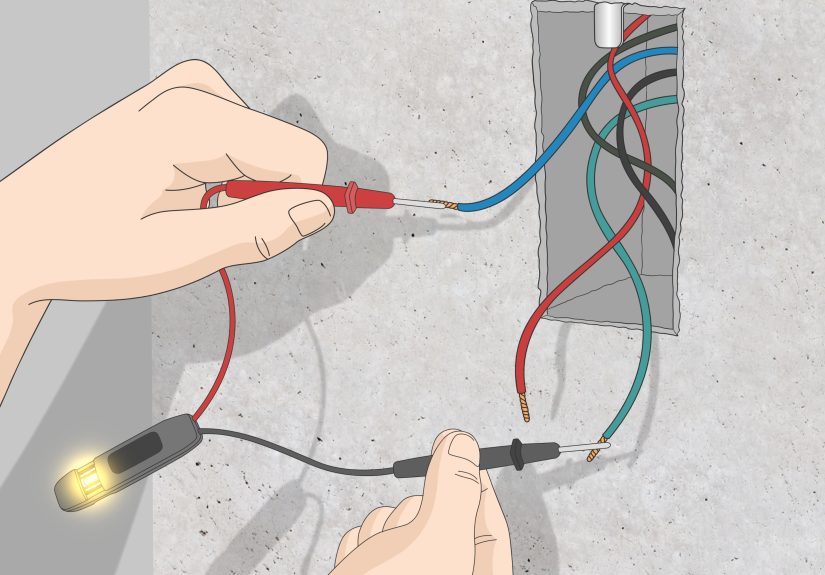
Measure Voltage First
Voltage is measured in parallel. That means you place the probes across two points, such as across a battery, across a resistor, or between a power rail and ground. If the expected voltage is missing, too low, too high, or unstable, you have learned something important immediately.
Start with the power source. Is the supply producing the expected voltage? Then move downstream. Is that voltage reaching the regulator input? Is the regulator output correct? Is the microcontroller getting power? Voltage testing helps you identify exactly where the electrical trail goes cold.
Why Voltage Testing Is So Powerful
A circuit can have perfect continuity and still fail completely if the wrong voltage is present. A corroded connector, a weak battery, a failed regulator, or excessive voltage drop under load can all make a circuit behave badly while still looking physically intact.
Voltage measurements also help confirm bias points in analog circuits and logic levels in digital circuits. If a transistor base should be around a certain threshold and it is sitting near zero, you have found a clue. If a digital line is stuck between clear high and clear low, the circuit is trying to tell you something unpleasant.
Current Measurement: Useful but More Invasive
Current measurements are valuable, but they demand more respect. Unlike voltage, current is measured in series. That means you must open the circuit and insert the meter so current flows through it. Use the correct input jack, start with the highest safe range, and never place a meter set to current mode directly across a voltage source unless you enjoy blown fuses and regret.
Current testing is especially helpful when:
- a device draws too much current and overheats,
- a battery-powered project dies too quickly,
- a subsystem is not turning on and appears to draw no current,
- you want to compare real power consumption against design expectations.
A Smart Workflow for Voltage and Current
In most troubleshooting jobs, check voltage before current. Voltage measurements are safer, faster, and less disruptive. Current measurements come next if the voltage looks fine but the circuit still behaves strangely.
Example: A motor driver board powers up, but the motor never spins. You measure the supply rail and confirm the board has 12 volts. Then you check the control signal and see it changes as expected. Finally, you measure current through the motor branch and find almost none. That points to an open connection, a failed transistor, or a broken motor winding.
3. Trace Signals with an Oscilloscope
When continuity and DC voltage measurements are not enough, an oscilloscope becomes the hero of the bench. A multimeter tells you average values. An oscilloscope shows what the signal is doing over time. That is a huge difference.
What an Oscilloscope Reveals
An oscilloscope lets you see waveforms, glitches, ripple, timing errors, ringing, noise, and missing pulses. If a clock signal is supposed to be a clean square wave and instead looks like a sad hill range, the scope will show it. If a power rail has ripple that is upsetting your circuit, the scope will expose it. If a serial line is active but corrupted, the scope lets you inspect the shape and timing.
This makes it ideal for:
- digital clock and data lines,
- audio and sensor signals,
- PWM outputs,
- power-supply ripple checks,
- timing-related bugs that a multimeter cannot see.
How to Use It Without Making Things Worse
Connect the probe ground clip to the correct circuit ground reference, then place the probe tip on the test point. On many bench oscilloscopes, the probe ground is tied to earth ground. That means a careless connection can create a short or ground loop. In other words, the oscilloscope is helpful, but it is not psychic. You still have to connect it intelligently.
Choose an appropriate volts-per-division setting, set a reasonable time base, and use triggering so the waveform remains stable on screen. Also compensate the probe correctly if your scope and probe require it. A badly compensated probe can make a good signal look suspicious, which is rude behavior from your tools.
When the Scope Solves the Mystery
Imagine a sensor board that powers on and passes continuity checks, but the microcontroller keeps missing input events. A meter shows the sensor output averages about 2.5 volts, which sounds plausible. But an oscilloscope reveals the real problem: the signal is full of narrow spikes and noise bursts that never settle cleanly. Suddenly the bug is no longer invisible.
Example: A switching regulator outputs the correct nominal voltage on a multimeter, but the attached logic resets randomly. On the scope, the rail shows excessive ripple and occasional dips during load changes. The regulator is not dead, but it is absolutely not behaving.
The Best Order to Test a Circuit
If you want a practical troubleshooting sequence, use this order:
- Inspect first. Look for burnt parts, reversed components, cracked solder joints, loose connectors, and wrong part values.
- Check continuity and resistance with power off. Confirm fuses, switches, traces, grounds, and obvious shorts or opens.
- Measure voltage with power on. Verify supply rails and key nodes.
- Measure current if needed. Use this to confirm load behavior or power consumption.
- Use an oscilloscope for signal tracing. This is where timing, noise, and dynamic problems come out of hiding.
This workflow saves time because it starts with the least invasive and most common checks. It also reduces the chance that you will chase a complicated signal problem when the real issue is just a broken ground wire pretending to be important.
Common Circuit Testing Mistakes to Avoid
- Using the wrong meter mode or probe jack.
- Skipping the schematic and guessing your way through the board.
- Measuring current by accident when you meant to measure voltage.
- Ignoring the circuit ground reference.
- Testing resistance on a live circuit.
- Assuming the power supply is fine because the indicator LED is on.
- Believing one reading without cross-checking with another method.
The best troubleshooters are not just careful; they are skeptical. They trust measurements, but they also verify them. If a reading makes no sense, they do not force reality to match it. They check probe placement, meter settings, component orientation, and whether the reference point is actually what they think it is.
Real-World Experience: What Testing Circuits Actually Feels Like
Anyone can memorize that continuity is for unpowered circuits and voltage is measured in parallel, but real experience with circuit testing teaches a deeper lesson: the first reading is rarely the whole story. The first reading is more like the opening line of a mystery novel. Interesting, useful, and sometimes dramatically misleading.
One of the most common beginner experiences is discovering that a circuit can look perfect and still be totally wrong. The solder joints shine. The parts are in neat rows. The wires are color-coded like a tiny electrical rainbow. And yet the thing does not work. That is the moment when testing stops being a chapter in a manual and becomes a survival skill. You grab the meter, check continuity, and realize a trace never connected where you thought it did. Suddenly the board is no longer “haunted.” It is just incomplete.
Another classic experience is learning how often power problems hide in plain sight. A circuit may have a battery attached, a regulator installed, and an LED cheerfully glowing, but one rail farther down the board is sitting at the wrong voltage. That teaches you not to test only the obvious point. Test the source, then the next stage, then the next. Power distribution is like plumbing: if the pressure vanishes halfway through the building, checking only the water tank is not enough.
Then there is the humbling moment when you use current mode incorrectly for the first time. Almost everyone who spends enough time around multimeters eventually blows a fuse, gasps, and learns a permanent lesson about meter jacks. It is an annoying lesson, but a memorable one. After that, you start glancing at the dial and probe ports with the same seriousness normally reserved for legal contracts and suspicious text messages.
Oscilloscope experience is a different kind of education. The first time you use one, the display can look like abstract art made by a caffeinated squirrel. But after a while, patterns start to make sense. A clock looks crisp. A noisy rail looks messy. A PWM signal becomes obvious. You begin to understand that a multimeter gives you a summary, while a scope gives you the actual drama. That difference changes how you think. You stop asking only, “Is voltage present?” and start asking, “Is the signal clean, timed correctly, and stable under load?”
Experience also teaches patience. Circuits do not care whether you are in a hurry. The fastest path to a solution is usually the calmest one: inspect, test, compare, isolate, repeat. The technicians who look magical are often just methodical. They do not randomly poke. They form a theory, test it, and keep narrowing the problem until the guilty part has nowhere left to hide.
Most of all, working with real circuits teaches confidence. Not the loud kind. The quiet kind. The kind that comes from knowing that even if a board fails, you have tools and a process to understand why. And honestly, that is one of the most satisfying feelings in electronics. Today it is a dead sensor board. Tomorrow it is a stubborn power supply. Eventually, you stop seeing broken circuits as disasters and start seeing them as puzzles with very tiny, very measurable clues.
Conclusion
If you want to test a circuit effectively, remember the big three. Use continuity and resistance to check the path when the power is off. Use voltage and current measurements to verify how power moves through the live circuit. Use an oscilloscope when the problem involves timing, noise, ripple, or signal behavior that a multimeter cannot reveal.
That combination covers most real-world troubleshooting jobs, from simple hobby projects to more serious bench diagnostics. Start with the safest and simplest checks, move logically, and let the readings guide you. Electronics may be complicated, but testing a circuit does not have to feel like translating ancient prophecies. Most of the time, it is just a matter of asking the right questions in the right order.